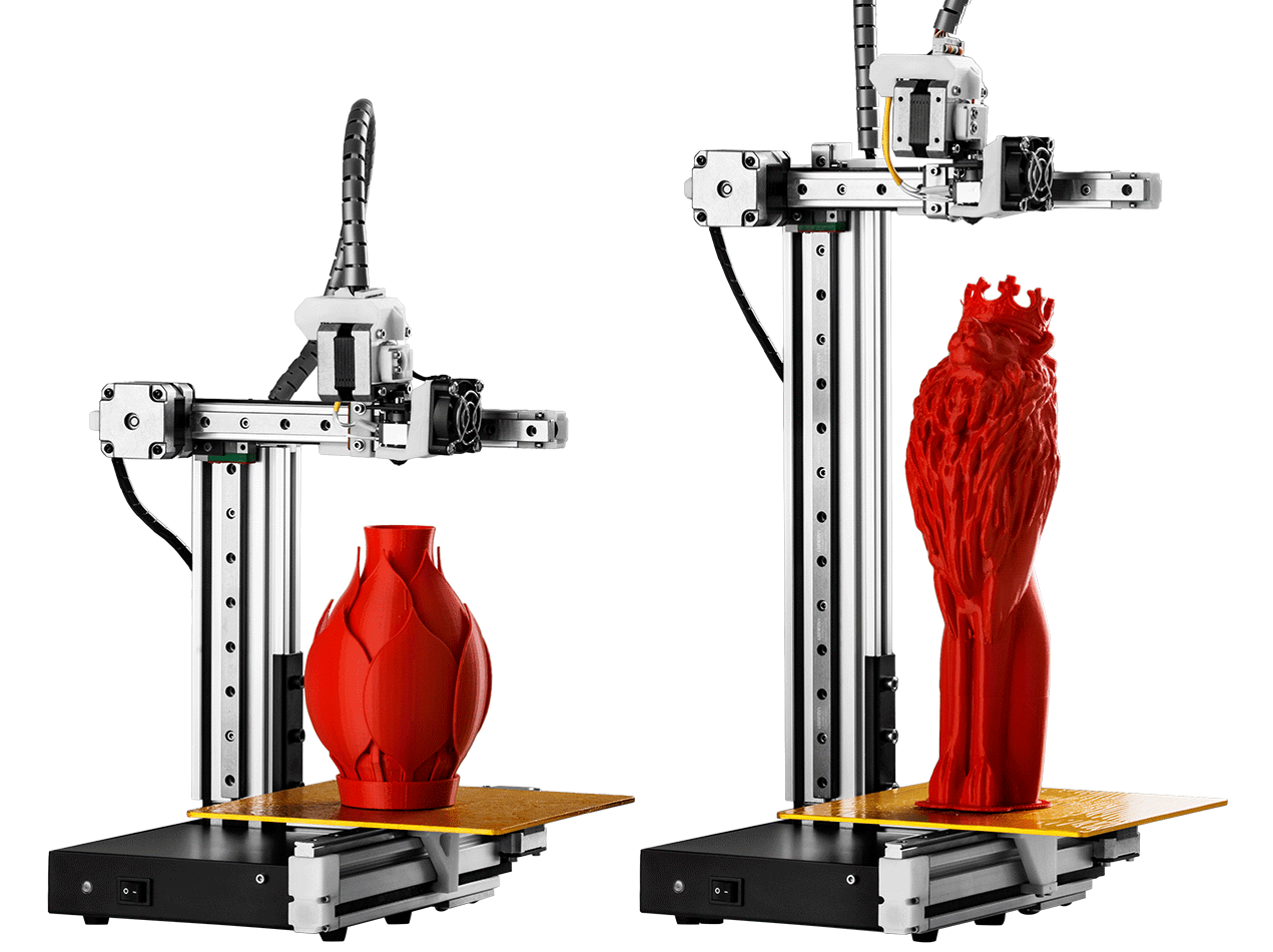

The upper bed temperature is limited to the 80s and after a long warm up using the stock Cetus power supply. M307 H0 B0 S0.45 F200 it heats to 55C at the same time as the nozzle get to 215C. My 200W 24V silicone bed heater needed a lower duty cycle and higher PWM frequency to not trip the 120W Cetus AC adapter’s internal short detection circuit. I find that with 0.1mm layers the washboard surface texture increases while it is very hard to see when printing with 0.15 and thicker layers. Any lower does not improve the print finish and higher adds an annoying minor washboard texture to the print surface. The extruder motor rotor is shorter and scaling the axis motor current you get a drive current of about 333ma. The axis motor currents can be 450ma any lower does not improve the print finish and at 475ma they start making noise. Measuring thread geometry is a good extrusion test and it quickly reveals temperature, layer height, filament brand, colour etc. It’s like a micrometer in that it measures the clearance between the printed nut and bolt threads. The steps/mm is the iterative result is from a printing nuts and bolts sliced with prusa. I also have the warranty replacement MK3 style but the prints were just not as good so I eventually repaired the original. Extrusion steps for the original MK2 extruder mechanism that has a filament release lever is 1650 steps/mm. I choose 256 micro stepping without interpolation. Could be sensor jitter or CPU capture jitter, anyway it is very repeatable if done extremely slowly.Īfter a bunch of tuning I converged on a few variables that might be useful to others. The resulting trigger position is very repeatable and any faster results in the inductive trigger position having 2 or more nearby but stable values.

The homing is done in 2 passes, fast and an extremely slow second pass (F0.1). The diodes are wired so they can only pull down the Duet input pin while the inductive sensor output signal swings from 0.6V to 24V. Looking at the numbers I believe the lower forward diode voltage drop meets the worst case Duet input voltage thresholds, regardless it works fine. To interface the inductive sensors output to the Duet I used Schottky diodes. All three of my inductive sensors are stationery requiring Z be homed before Y, however, this keeps the accelerating mass down and the sensor wiring stationary. I choose inductive sensors for homing all the axes. I designed some parts for my Cetus Duet2 WIFI conversionĭon’t judge me but I started this about a year ago in the middle of some online configurator tool issues and had to modify the config files the hard way, much easier now.


 0 kommentar(er)
